Once a chip is manufactured, it can be a tricky task if any functional issues are discovered or some feature enhancements need to be made in the next build. However, with a spare unit, these changes can be a breeze.
So what exactly is a backup unit? In short, spare cells are cells like DFF (flip-flop), NAND, AND, XOR, INV (inverter), etc. that are pre-placed in the design. They do not perform any logical operations and simply exist as a filling unit.
Spare unit:
Alternate cells usually consist of a set of standard cells, including inverters, buffers, NAND, NOR, AND gates, OR gates, XOR gates, multiplexers, flip-flops, and more.
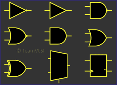
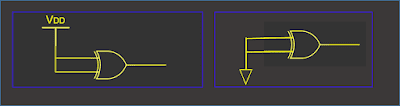
Of course, there may also be some specially designed configurable spare units. The inputs of these backup units are tied together via connecting units tied to power (VDD) or ground (VSS), while the outputs are left floating. This is to avoid floating inputs being affected by noise, resulting in unnecessary switching actions and additional power consumption. A set of spare units is shown below.
Purpose of spare unit:
The primary role of the spare unit is to minimize mask changes when modifications or improvements to chip functionality are required. We can take advantage of already pre-placed spare cells and only modify the metal interconnects without changing the base layer. By performing a metal ECO (Engineering Change Order), we can modify the interconnect metal connections and utilize spare cells without making mask changes to the base layer. This way we only have to change the mask for a small amount of metal rather than having to re-manufacture the entire chip. This not only saves costs, but also saves a lot of time.
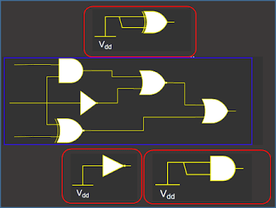
For example, suppose in the above circuit we need to replace the last OR gate in the middle part of the circuit with an EXOR or AND gate, we can rewire the spare unit close here with just a metal ECO.
Layout of spare unit:
Alternate cells can be added to the design in netlist form or using the PnR tool's commands (or graphical user interface). In physical design, we usually tend to use tool commands to add spare cells. These cells are added before the standard cells are placed throughout the design.
For example, in tools such as Innovus and ICC, we can use the corresponding commands to add spare units. This way, spare units can be conveniently placed in the design.
Innovus tools:
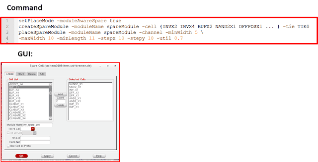
ICC Tools:

Advantages and Disadvantages of Spare Units:
There are many advantages to using a spare unit, but there are also some disadvantages. Let's take a look at its advantages first:
First, spare units are highly reusable. Because we only need to change a small amount of metal and transmission masks, we can reuse the base layer mask and save chip manufacturing costs.
Second, backup units provide great flexibility. We can easily make small changes to the design without having to remake the entire chip.
In addition, backup units save costs and time. For new design projects, we only need to change a small number of interconnect masks, thus saving a lot of chip manufacturing costs. With metal ECO, we do not need to conduct a complete design cycle, thus saving valuable design time.
Of course, backup units also have some disadvantages:
First, the use of spare cells increases leakage power consumption in the design. This is because the backup unit will add some unnecessary switching actions, resulting in additional power consumption.
Additionally, spare units take up some area in the design. This means that additional space is required in the design to place spare units, which may have a certain impact on the overall quality of the optimization results.
To sum up, spare cells play an important role in physical design. They can help us solve problems in the chip manufacturing process
thank you
[1] https://teamvlsi.com/2020/08/spare-cells-in-physical-design.html
[2] https://blog.csdn.net/qq_21842097/article/details/121745578